According to the <NTC Thermistor Improves Circuit of Poor Tracking Error of Optical Module-2>, illustrated by the following example:
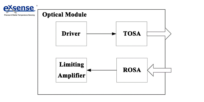
The optical module in the figure includes a optical transmitting device TOSA of transmit channel, a drive for driving a laser of a TOSA, and a sequentially connected optical transceiver device ROSA and a limiting amplifier for the receiving channel. As shown in Figure 1, driver includes laser drive chip, laser driver chip is connected to the laser of TOSA, the laser driver chip is connected to the optical power first thermistor, the optical power first thermistor is NTC thermistor RNTC. At room temperature 25℃, the resistance value of thermistor RNTC is 50KΩ, at high temperature 90℃, the resistance value is 8KΩ, the resistance value of NTC thermistor RNTC decreases gradually with the increase of temperature.
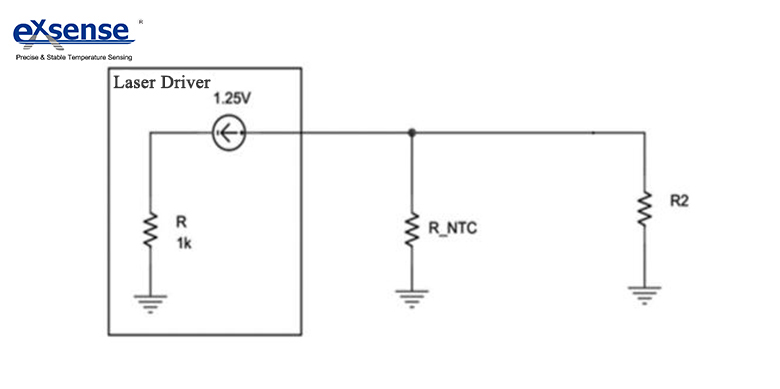
The NTC thermistor RNTC is installed in the peripheral circuit of the laser drive chip. For the general laser driver chip, there must be a peripheral circuit, the thermistor R is the internal resistance of the laser driver chip, which is determined by the internal structure of the laser driver chip. The circuit also includes optical power second thermistor R2, optical power second thermistor R2 and optical power first thermistor RNTC is paralleled together to form the peripheral optical power resistor R of laser driver chip, where R, RNTC and R2 meet the following relation:
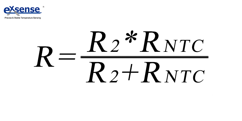
The thermistor R2 and the thermistor RNTC is together to form the peripheral optical power thermistor R of the laser driver chip, and the relation between bias current IBIAS and thermistor R added to the output of laser driver chip is shown in the following formula:
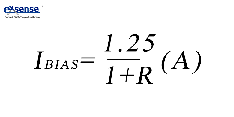
The resistance of NTC thermistor selected here decreases with the increase of temperature, and at high temperature, the bias current IBIAS of the laser driver chip will increase and then increase the output optical power value of the laser appropriately.

The figure above is a schematic diagram of the bias current between the existing optical module and the optical module after adopting this method under the condition of maintaining the light power constant. Among them, the 90℃IM curve indicates that the laser in the case of high temperature (90 ℃), the bias current BISA repaired to maintain normal optical power; Im@ith+20ma|90 curve indicates that in the case of high temperature (90 ℃), actual measured optical power bias current BIAS; bias after NTC added curve indicates that in the case of high temperature (90 ℃), actual measured optical power bias current BIAS after adding the NTC thermistor. Thus we can see that, the Im@ith+20ma|90 curve differs greatly from the 90℃IM curve, while the bias after NTC added curve is more consistent with the 90℃IM curve, which shows that adding NTC thermistor can improve circuit of poor tracking error of optical module. Due to the addition of NTC thermistor, so that the optical module output light power to recover to the normal working requirement in the high temperature time to reach the required range, avoids the waste of TOSA or BOSA devices, and saves the production cost.